

Szczegóły produktu można znaleźć w specyfikacjach.
SN74LS90N
Product Overview
- Category: Integrated Circuit (IC)
- Use: Counter
- Characteristics: TTL Logic, 4-bit Decade Counter
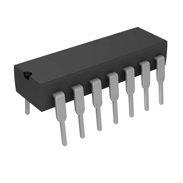
- Package: DIP-14 (Dual In-Line Package with 14 pins)
- Essence: The SN74LS90N is a synchronous, presettable, 4-bit decade counter that counts in decimal from 0 to 9. It is widely used in digital electronics for counting applications.
- Packaging/Quantity: Available in tubes or reels, with a quantity of 25 units per tube/reel.
Specifications
- Supply Voltage: 4.75V to 5.25V
- Logic Family: LS-TTL (Low Power Schottky Transistor-Transistor Logic)
- Operating Temperature Range: 0°C to 70°C
- Propagation Delay: 15ns (typical)
- Maximum Clock Frequency: 42MHz
Detailed Pin Configuration
The SN74LS90N has a total of 14 pins, each serving a specific purpose:
- VCC - Positive power supply voltage
- GND - Ground reference
- CP - Clock input
- MR - Master Reset input
- QA - Output A
- QB - Output B
- QC - Output C
- QD - Output D
- RC - Ripple Carry output
- RCO - Ripple Carry output enable
- LT - Lamp Test input
- BI/RBO - Borrow-In/Borrow-Out
- A - Preset input A
- B - Preset input B
Functional Features
- Synchronous operation allows precise control over the counting sequence.
- Presettable inputs (A and B) enable the user to set the initial count value.
- Ripple Carry output (RC) provides a carry signal for cascading multiple counters.
- Borrow-In/Borrow-Out (BI/RBO) allows the SN74LS90N to be used as a BCD subtractor.
Advantages and Disadvantages
Advantages
- Low power consumption due to LS-TTL technology.
- Compact DIP-14 package allows easy integration into various circuit designs.
- Precise counting sequence with synchronous operation.
Disadvantages
- Limited count range from 0 to 9.
- Not suitable for applications requiring larger counter sizes.
Working Principles
The SN74LS90N operates based on the principle of synchronous counting. The clock input (CP) triggers the counter to increment its count value by one on each rising edge of the clock signal. The preset inputs (A and B) allow the user to set the initial count value. The outputs (QA, QB, QC, QD) represent the current count in binary-coded decimal (BCD) format.
Detailed Application Field Plans
The SN74LS90N finds applications in various fields, including:
- Digital frequency dividers
- Industrial automation systems
- Electronic voting machines
- Digital clocks and timers
- Traffic light control systems
Detailed and Complete Alternative Models
There are several alternative models available that offer similar functionality to the SN74LS90N. Some popular alternatives include:
- CD4017 - CMOS Decade Counter/Divider IC
- 74HC390 - High-Speed CMOS Logic Dual Decade Counter
- CD4026 - CMOS Decade Counter/Divider with Decoded 7-Segment Display Outputs
These alternative models can be considered based on specific project requirements and compatibility with other components.
Word count: 408 words
Wymień 10 typowych pytań i odpowiedzi związanych z zastosowaniem SN74LS90N w rozwiązaniach technicznych
Sure! Here are 10 common questions and answers related to the application of SN74LS90N in technical solutions:
Q: What is SN74LS90N? A: SN74LS90N is a decade counter IC (integrated circuit) that can count from 0 to 9 using four flip-flops.
Q: What is the purpose of using SN74LS90N in technical solutions? A: SN74LS90N is commonly used for counting applications, frequency division, and timekeeping circuits.
Q: How does SN74LS90N work? A: SN74LS90N works by sequentially incrementing its output pins based on clock pulses received at its input pin.
Q: What is the maximum clock frequency supported by SN74LS90N? A: SN74LS90N can handle clock frequencies up to 25 MHz.
Q: Can SN74LS90N be cascaded to count beyond 9? A: Yes, multiple SN74LS90N ICs can be cascaded together to count beyond 9 by connecting the carry-out pin of one IC to the clock input of the next IC.
Q: What is the power supply voltage range for SN74LS90N? A: SN74LS90N operates with a power supply voltage range of 4.75V to 5.25V.
Q: Does SN74LS90N require any external components for operation? A: SN74LS90N requires an external clock signal and power supply, but it doesn't need any additional components for basic functionality.
Q: Can SN74LS90N be used in both digital and analog circuits? A: No, SN74LS90N is a digital IC and is primarily used in digital circuits.
Q: What are the output pins of SN74LS90N used for? A: The four output pins (QA, QB, QC, QD) of SN74LS90N represent the binary count from 0 to 9.
Q: Are there any limitations or considerations when using SN74LS90N? A: Some considerations include proper power supply voltage, clock frequency, and noise immunity. Additionally, care should be taken to avoid exceeding the maximum ratings specified in the datasheet.
Please note that these answers are general and may vary depending on specific circuit requirements and application scenarios.