

Szczegóły produktu można znaleźć w specyfikacjach.
SN74AUC1G80DBVR
Product Overview
- Category: Integrated Circuit (IC)
- Use: Logic Gate
- Characteristics: Single Positive Edge-Triggered D-Type Flip-Flop
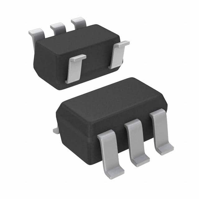
- Package: SOT-23-6
- Essence: High-speed, low-power consumption flip-flop
- Packaging/Quantity: Tape and Reel, 3000 units per reel
Specifications
- Supply Voltage Range: 0.8V to 3.6V
- Input Voltage Range: -0.5V to VCC + 0.5V
- Operating Temperature Range: -40°C to 85°C
- Propagation Delay: 2.7ns (typical)
- Output Drive Capability: ±24mA at 3.3V
- Power Dissipation: 4.5mW (typical)
Detailed Pin Configuration
The SN74AUC1G80DBVR has a total of six pins arranged as follows:
____
   GND|    |VCC
   D  |    |Q
   CP |    |CLR
   PR |    |NC
      |____|
- GND: Ground pin
- VCC: Power supply pin
- D: Data input pin
- Q: Flip-flop output pin
- CP: Clock pulse input pin
- CLR: Clear input pin
- PR: Preset input pin
- NC: No connection pin
Functional Features
The SN74AUC1G80DBVR is a single positive edge-triggered D-type flip-flop. It operates with a supply voltage range of 0.8V to 3.6V, making it suitable for low-power applications. The flip-flop has a propagation delay of 2.7ns, allowing for high-speed operation. It also has a high output drive capability of ±24mA at 3.3V, enabling it to drive external loads efficiently.
Advantages and Disadvantages
Advantages: - Low power consumption - High-speed operation - Compact package size - Wide supply voltage range
Disadvantages: - Limited input voltage range - Single flip-flop functionality
Working Principles
The SN74AUC1G80DBVR operates as a positive edge-triggered D-type flip-flop. The data input (D) is latched into the flip-flop on the rising edge of the clock pulse (CP). The output (Q) reflects the state of the input at the time of the clock pulse. The clear (CLR) and preset (PR) inputs allow for resetting or setting the flip-flop to a specific state.
Detailed Application Field Plans
The SN74AUC1G80DBVR can be used in various applications, including but not limited to: - Digital communication systems - Microcontrollers - Data storage devices - Signal processing circuits - Battery-powered devices
Detailed and Complete Alternative Models
Some alternative models that offer similar functionality to the SN74AUC1G80DBVR include: - SN74AUC1G80DCKR - SN74AUC1G80YZPR - SN74AUC1G80DRLR - SN74AUC1G80DRLRG4
These models have comparable specifications and pin configurations, providing flexibility in choosing the most suitable option for specific design requirements.
Word count: 346 words
Wymień 10 typowych pytań i odpowiedzi związanych z zastosowaniem SN74AUC1G80DBVR w rozwiązaniach technicznych
Sure! Here are 10 common questions and answers related to the application of SN74AUC1G80DBVR:
Q1: What is SN74AUC1G80DBVR? A1: SN74AUC1G80DBVR is a single positive-edge-triggered D-type flip-flop with clear, designed for 1.65-V to 5.5-V VCC operation.
Q2: What is the purpose of SN74AUC1G80DBVR? A2: SN74AUC1G80DBVR is used to store and manipulate digital data in electronic circuits. It can be used in various applications such as counters, registers, and memory elements.
Q3: What is the voltage range supported by SN74AUC1G80DBVR? A3: SN74AUC1G80DBVR supports a voltage range from 1.65V to 5.5V.
Q4: What is the maximum operating frequency of SN74AUC1G80DBVR? A4: The maximum operating frequency of SN74AUC1G80DBVR is typically around 500 MHz.
Q5: How many inputs and outputs does SN74AUC1G80DBVR have? A5: SN74AUC1G80DBVR has one data input (D), one clock input (CLK), one clear input (CLR), and one output (Q).
Q6: Can SN74AUC1G80DBVR be cascaded to create larger memory elements? A6: Yes, multiple SN74AUC1G80DBVR flip-flops can be cascaded together to create larger memory elements or shift registers.
Q7: What is the power consumption of SN74AUC1G80DBVR? A7: SN74AUC1G80DBVR has low power consumption, making it suitable for battery-powered applications.
Q8: Is SN74AUC1G80DBVR compatible with other logic families? A8: Yes, SN74AUC1G80DBVR is compatible with a wide range of logic families, including CMOS and TTL.
Q9: Can SN74AUC1G80DBVR operate in harsh environments? A9: SN74AUC1G80DBVR is designed to operate in a wide temperature range and can withstand moderate levels of shock and vibration.
Q10: Are there any application notes or reference designs available for SN74AUC1G80DBVR? A10: Yes, Texas Instruments provides application notes and reference designs that demonstrate the use of SN74AUC1G80DBVR in various technical solutions. These resources can be found on their website.