

Szczegóły produktu można znaleźć w specyfikacjach.
SN74ACT564DBR
Product Overview
- Category: Integrated Circuit (IC)
- Use: Digital Logic
- Characteristics: Octal D-Type Flip-Flop with 3-State Outputs
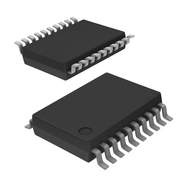
- Package: SSOP-20
- Essence: High-speed, low-power consumption flip-flop
- Packaging/Quantity: Tape and Reel, 2500 pieces per reel
Specifications
- Supply Voltage Range: 4.5V to 5.5V
- High-Speed Operation: 7.5 ns maximum propagation delay
- Low Power Consumption: 10µA maximum ICC
- Output Drive Capability: ±24mA at 5V
- Operating Temperature Range: -40°C to +85°C
Detailed Pin Configuration
- GND - Ground
- D0 - Data Input 0
- D1 - Data Input 1
- D2 - Data Input 2
- D3 - Data Input 3
- D4 - Data Input 4
- D5 - Data Input 5
- D6 - Data Input 6
- D7 - Data Input 7
- CP - Clock Pulse Input
- OE - Output Enable Input
- Q0 - Output 0
- Q1 - Output 1
- Q2 - Output 2
- Q3 - Output 3
- Q4 - Output 4
- Q5 - Output 5
- Q6 - Output 6
- Q7 - Output 7
- VCC - Power Supply
Functional Features
- Octal D-type flip-flop with 3-state outputs
- Positive-edge triggered clock input
- Asynchronous clear input for all flip-flops
- 3-state outputs for bus-oriented applications
- Outputs can be disabled using the output enable input
Advantages and Disadvantages
Advantages: - High-speed operation allows for efficient data processing - Low power consumption reduces energy usage - 3-state outputs enable bus-oriented applications - Asynchronous clear input provides flexibility in resetting the flip-flops
Disadvantages: - Limited supply voltage range (4.5V to 5.5V) - May not be suitable for applications requiring a wider operating temperature range
Working Principles
The SN74ACT564DBR is an octal D-type flip-flop with 3-state outputs. It operates on positive-edge triggered clock input, allowing for synchronized data storage. The asynchronous clear input resets all flip-flops simultaneously when activated. The 3-state outputs enable multiple devices to share a common bus, providing flexibility in data transmission.
Detailed Application Field Plans
The SN74ACT564DBR is commonly used in various digital logic applications, including but not limited to: - Data storage and retrieval systems - Address decoding circuits - Bus interface units - Memory modules - Microprocessor-based systems
Detailed and Complete Alternative Models
- SN74ACT574DBR: Octal D-Type Flip-Flop with 3-State Outputs, SSOP-20 package
- SN74ACT563DBR: Octal Transparent D-Type Latches with 3-State Outputs, SSOP-20 package
- SN74ACT565DBR: Octal D-Type Flip-Flop with Clear, SSOP-20 package
- SN74ACT566DBR: Octal D-Type Flip-Flop with Clear and 3-State Outputs, SSOP-20 package
These alternative models offer similar functionality and characteristics to the SN74ACT564DBR, providing options for different design requirements.
Word count: 346 words
Wymień 10 typowych pytań i odpowiedzi związanych z zastosowaniem SN74ACT564DBR w rozwiązaniach technicznych
Sure! Here are 10 common questions and answers related to the application of SN74ACT564DBR:
Q: What is SN74ACT564DBR? A: SN74ACT564DBR is a type of octal D-type flip-flop with 3-state outputs, commonly used in digital circuits.
Q: What is the maximum operating voltage for SN74ACT564DBR? A: The maximum operating voltage for SN74ACT564DBR is 5.5V.
Q: How many flip-flops are there in SN74ACT564DBR? A: SN74ACT564DBR consists of 8 individual D-type flip-flops.
Q: What is the output current capability of SN74ACT564DBR? A: The output current capability of SN74ACT564DBR is typically 24mA.
Q: Can SN74ACT564DBR be used in high-speed applications? A: Yes, SN74ACT564DBR is designed for high-speed operation and can be used in such applications.
Q: Does SN74ACT564DBR have any built-in protection features? A: SN74ACT564DBR has built-in diode clamps to minimize the effects of electrostatic discharge (ESD).
Q: What is the typical propagation delay of SN74ACT564DBR? A: The typical propagation delay of SN74ACT564DBR is around 6ns.
Q: Can SN74ACT564DBR be used in both parallel and serial data transfer applications? A: Yes, SN74ACT564DBR can be used in both parallel and serial data transfer applications.
Q: What is the power supply voltage range for SN74ACT564DBR? A: The power supply voltage range for SN74ACT564DBR is typically between 4.5V and 5.5V.
Q: Is SN74ACT564DBR compatible with other logic families? A: Yes, SN74ACT564DBR is compatible with a wide range of logic families, including TTL, CMOS, and LVTTL.
Please note that the answers provided here are general and may vary depending on specific datasheet specifications and application requirements.