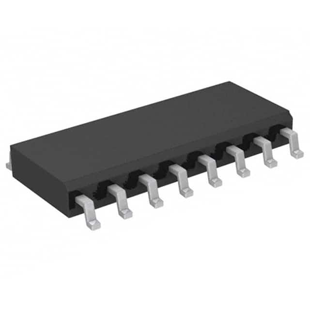
Szczegóły produktu można znaleźć w specyfikacjach.

HCF4014M013TR
Product Overview
Category
HCF4014M013TR belongs to the category of integrated circuits (ICs).
Use
This product is commonly used in digital electronics and is specifically designed as a 8-bit static shift register.
Characteristics
- The HCF4014M013TR is a high-speed CMOS device.
- It operates at a wide voltage range, making it suitable for various applications.
- This IC has a low power consumption, making it energy-efficient.
- It offers excellent noise immunity, ensuring reliable performance even in noisy environments.
Package
The HCF4014M013TR is available in a small outline package (SO-14) which provides easy integration into electronic circuits.
Essence
The essence of this product lies in its ability to store and shift data bits in a sequential manner.
Packaging/Quantity
The HCF4014M013TR is typically packaged in reels containing 2500 units per reel.
Specifications
- Supply Voltage: 3V to 18V
- Input Voltage: -0.5V to VDD + 0.5V
- Output Voltage: -0.5V to VDD + 0.5V
- Operating Temperature Range: -40°C to 125°C
- Maximum Clock Frequency: 25MHz
Detailed Pin Configuration
The HCF4014M013TR has a total of 14 pins. The pin configuration is as follows:
- Serial Data Input (DS)
- Parallel Data Inputs (D0-D7)
- Clock Input (CP)
- Master Reset Input (MR)
- Serial Data Output (QH')
- Output Enable (OE)
- Ground (GND)
- Q0 Output
- Q1 Output
- Q2 Output
- Q3 Output
- Q4 Output
- Q5 Output
- VDD (Supply Voltage)
Functional Features
- The HCF4014M013TR can be used to shift data bits in a serial-in, parallel-out manner.
- It has a master reset input that allows the user to clear the register.
- The output enable pin enables or disables the outputs.
- This IC operates on positive-edge clocking.
Advantages and Disadvantages
Advantages
- High-speed operation allows for efficient data shifting.
- Wide voltage range makes it versatile for different applications.
- Low power consumption ensures energy efficiency.
- Excellent noise immunity guarantees reliable performance.
Disadvantages
- Limited number of outputs (6) may restrict certain applications requiring more outputs.
- Requires external components for proper functionality.
Working Principles
The HCF4014M013TR works by receiving data through the serial data input pin (DS) and shifting it into the register on each rising edge of the clock input (CP). The shifted data is then available at the parallel data outputs (Q0-Q5). The master reset input (MR) can be used to clear the register, and the output enable pin (OE) controls the output state.
Detailed Application Field Plans
The HCF4014M013TR can be applied in various fields, including:
- Digital communication systems
- Data storage devices
- Industrial automation
- Consumer electronics
- Automotive electronics
Detailed and Complete Alternative Models
Some alternative models to the HCF4014M013TR include:
- CD4014BE
- SN74HC595N
- 74HC164N
- CD74HC4094E
- MC74HC595AN
These alternative models offer similar functionality and can be used as substitutes depending on specific requirements.
In conclusion, the HCF4014M013TR is a high-speed CMOS integrated circuit used as an 8-bit static shift register. It offers various advantages such as wide voltage range, low power consumption, and excellent noise immunity. Its detailed pin configuration, functional features, working principles, application field plans, and alternative models make it a versatile choice for digital electronics applications.
Wymień 10 typowych pytań i odpowiedzi związanych z zastosowaniem HCF4014M013TR w rozwiązaniach technicznych
Sure! Here are 10 common questions and answers related to the application of HCF4014M013TR in technical solutions:
Q: What is the HCF4014M013TR? A: The HCF4014M013TR is a 8-bit static shift register with parallel input and serial output, commonly used in digital circuits.
Q: What is the maximum clock frequency for the HCF4014M013TR? A: The maximum clock frequency for the HCF4014M013TR is typically around 25 MHz.
Q: How many parallel inputs does the HCF4014M013TR have? A: The HCF4014M013TR has 8 parallel inputs, labeled D0 to D7.
Q: Can I cascade multiple HCF4014M013TR shift registers together? A: Yes, you can cascade multiple HCF4014M013TR shift registers together to increase the number of bits.
Q: What is the power supply voltage range for the HCF4014M013TR? A: The power supply voltage range for the HCF4014M013TR is typically between 3V and 18V.
Q: Does the HCF4014M013TR have any built-in latches? A: Yes, the HCF4014M013TR has 8 built-in latches that hold the data at the parallel inputs until the next clock cycle.
Q: What is the typical propagation delay of the HCF4014M013TR? A: The typical propagation delay of the HCF4014M013TR is around 20 ns.
Q: Can I use the HCF4014M013TR in both serial-to-parallel and parallel-to-serial conversion applications? A: Yes, the HCF4014M013TR can be used for both serial-to-parallel and parallel-to-serial conversion.
Q: Does the HCF4014M013TR have any output enable pins? A: No, the HCF4014M013TR does not have any output enable pins. The outputs are always active.
Q: What is the package type of the HCF4014M013TR? A: The HCF4014M013TR is available in a 14-pin SOIC (Small Outline Integrated Circuit) package.
Please note that the answers provided here are general and may vary depending on the specific datasheet and manufacturer's specifications for the HCF4014M013TR.

