

Szczegóły produktu można znaleźć w specyfikacjach.
MC74VHCT259ADTR2G
Basic Information Overview
- Category: Integrated Circuit (IC)
- Use: Digital multiplexer/demultiplexer
- Characteristics:
- High-speed operation
- Low power consumption
- Wide operating voltage range
- Schmitt-trigger inputs for noise immunity
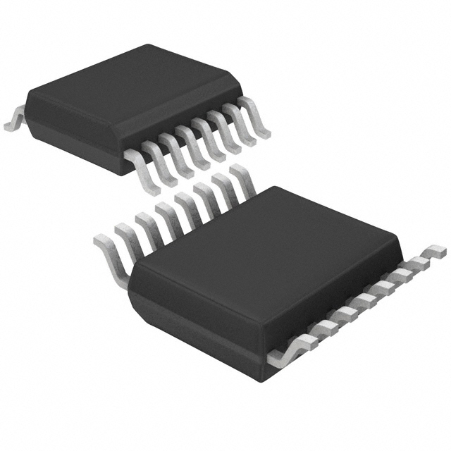
- Package: TSSOP-16
- Essence: This IC is a 8-bit addressable latch/shift register with 3-state outputs.
- Packaging/Quantity: Tape and Reel, 2500 units per reel
Specifications
- Supply Voltage Range: 2.0V to 5.5V
- Input Voltage Range: -0.5V to VCC + 0.5V
- Output Voltage Range: -0.5V to VCC + 0.5V
- Operating Temperature Range: -40°C to +85°C
- Maximum Clock Frequency: 74 MHz
Detailed Pin Configuration
- GND (Ground)
- D0 (Data Input 0)
- D1 (Data Input 1)
- D2 (Data Input 2)
- D3 (Data Input 3)
- D4 (Data Input 4)
- D5 (Data Input 5)
- D6 (Data Input 6)
- D7 (Data Input 7)
- MR (Master Reset)
- SH/LD (Shift/Load)
- CLK (Clock)
- OE (Output Enable)
- Q0 (Output 0)
- Q1 (Output 1)
- VCC (Supply Voltage)
Functional Features
- Addressable latch function: Allows individual data input and output control for each latch.
- Shift register function: Enables serial-to-parallel or parallel-to-serial data conversion.
- 3-state outputs: Provides high impedance state when disabled, allowing multiple devices to share a common bus.
Advantages
- High-speed operation allows for efficient data processing.
- Low power consumption makes it suitable for battery-powered applications.
- Wide operating voltage range provides flexibility in various electronic systems.
- Schmitt-trigger inputs ensure reliable operation in noisy environments.
Disadvantages
- Limited number of addressable latches (8-bit).
- Not suitable for applications requiring higher clock frequencies.
Working Principles
The MC74VHCT259ADTR2G is designed as an 8-bit addressable latch/shift register. It can operate in two modes: latch mode and shift mode. In latch mode, the data inputs are latched and stored in the internal registers based on the clock and latch control signals. In shift mode, the data is shifted through the internal registers based on the clock signal. The output enable signal controls the output state of the device.
Detailed Application Field Plans
- Data multiplexing/demultiplexing in digital systems.
- Serial-to-parallel or parallel-to-serial data conversion.
- Addressable memory storage and retrieval.
- Control signal generation and distribution.
Detailed and Complete Alternative Models
- SN74HC595N: 8-bit serial-in, parallel-out shift register with output latches.
- CD4015BE: Dual 4-stage static shift register with serial input and parallel output.
- 74HC164N: 8-bit serial-in, parallel-out shift register with asynchronous reset.
Note: These alternative models offer similar functionality but may have different specifications and pin configurations.
Word count: 346 words
Wymień 10 typowych pytań i odpowiedzi związanych z zastosowaniem MC74VHCT259ADTR2G w rozwiązaniach technicznych
Sure! Here are 10 common questions and answers related to the application of MC74VHCT259ADTR2G in technical solutions:
Q: What is MC74VHCT259ADTR2G? A: MC74VHCT259ADTR2G is a high-speed CMOS 8-bit addressable latch with 3-state outputs, commonly used in digital systems.
Q: What are the key features of MC74VHCT259ADTR2G? A: Some key features include high-speed operation, 3-state outputs, wide operating voltage range, and compatibility with TTL inputs.
Q: How can MC74VHCT259ADTR2G be used in technical solutions? A: It can be used for address decoding, data storage, bus interfacing, and other applications where latch functionality is required.
Q: What is the maximum operating frequency of MC74VHCT259ADTR2G? A: The maximum operating frequency is typically around 100 MHz, making it suitable for high-speed applications.
Q: Can MC74VHCT259ADTR2G handle both input and output signals? A: Yes, MC74VHCT259ADTR2G has separate pins for input and output signals, allowing bidirectional communication.
Q: What is the power supply voltage range for MC74VHCT259ADTR2G? A: The power supply voltage range is typically between 2V and 5.5V, making it compatible with a wide range of systems.
Q: Does MC74VHCT259ADTR2G have built-in protection features? A: Yes, MC74VHCT259ADTR2G has built-in ESD protection, which helps safeguard against electrostatic discharge.
Q: Can MC74VHCT259ADTR2G be cascaded to increase the number of addressable latches? A: Yes, multiple MC74VHCT259ADTR2G devices can be cascaded together to increase the number of addressable latches in a system.
Q: What is the typical power consumption of MC74VHCT259ADTR2G? A: The typical power consumption is low, making it suitable for battery-powered or energy-efficient applications.
Q: Is MC74VHCT259ADTR2G available in different package options? A: Yes, MC74VHCT259ADTR2G is available in various package options, such as SOIC, TSSOP, and PDIP, providing flexibility for different PCB designs.
Please note that the answers provided are general and may vary depending on specific datasheet specifications and application requirements.