

Szczegóły produktu można znaleźć w specyfikacjach.
MC10E112FNR2
Product Overview
- Category: Integrated Circuit (IC)
- Use: Logic Gate
- Characteristics: High-speed, ECL (Emitter-Coupled Logic) technology
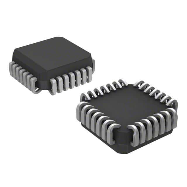
- Package: 28-pin PLCC (Plastic Leaded Chip Carrier)
- Essence: Dual 4-input NOR gate
- Packaging/Quantity: Tape and Reel, 2500 units per reel
Specifications
- Supply Voltage Range: -4.2V to -5.7V
- Input Voltage Range: -3.0V to -5.7V
- Output Voltage Range: -3.0V to -5.7V
- Operating Temperature Range: -40°C to +85°C
- Propagation Delay Time: 1.8 ns (typical)
- Output Current: ±24 mA (maximum)
Detailed Pin Configuration
The MC10E112FNR2 has a total of 28 pins, numbered as follows:
- VEE
- Q0
- Q1
- Q2
- Q3
- GND
- D0
- D1
- D2
- D3
- /OE
- /CLR
- /PRE
- /CLK
- CLK
- PRE
- CLR
- OE
- D3
- D2
- D1
- D0
- GND
- Q3
- Q2
- Q1
- Q0
- VCC
Functional Features
- Dual 4-input NOR gate with differential outputs
- High-speed operation suitable for demanding applications
- ECL technology ensures low power consumption and high noise immunity
- Differential inputs provide improved noise rejection and signal integrity
Advantages and Disadvantages
Advantages: - High-speed operation allows for efficient data processing - ECL technology provides excellent noise immunity - Differential outputs enhance signal quality - Suitable for applications requiring reliable logic gate functionality
Disadvantages: - Requires a negative power supply, limiting compatibility with certain systems - Higher power consumption compared to CMOS-based logic gates - Limited availability of alternative models due to specialized ECL technology
Working Principles
The MC10E112FNR2 operates based on the principles of Emitter-Coupled Logic. It utilizes differential inputs to compare and process signals, resulting in accurate logic gate functionality. The NOR gate configuration allows for logical OR operations on multiple inputs, providing flexibility in various digital circuits.
Detailed Application Field Plans
The MC10E112FNR2 is commonly used in high-speed data communication systems, such as telecommunications networks, where reliable logic gate functionality is crucial. It finds applications in:
- Data transmission and reception modules
- Signal processing units
- Network routers and switches
- Industrial automation systems
- Test and measurement equipment
Detailed and Complete Alternative Models
Due to the specialized ECL technology used in the MC10E112FNR2, alternative models with identical specifications may be limited. However, some alternative options that provide similar functionality include:
- MC100EP112: 4-input differential NOR gate
- MC100EL112: 4-input differential NOR gate
- MC100LVEL112: 4-input differential NOR gate
These alternatives can be considered based on specific system requirements and availability.
Word count: 345 words
Wymień 10 typowych pytań i odpowiedzi związanych z zastosowaniem MC10E112FNR2 w rozwiązaniach technicznych
Sure! Here are 10 common questions and answers related to the application of MC10E112FNR2 in technical solutions:
Q: What is MC10E112FNR2? A: MC10E112FNR2 is a specific type of integrated circuit (IC) that belongs to the MC10E series. It is commonly used in high-speed digital applications.
Q: What are the key features of MC10E112FNR2? A: Some key features of MC10E112FNR2 include differential inputs, ECL (Emitter-Coupled Logic) outputs, wide operating voltage range, and high-speed operation.
Q: What are the typical applications of MC10E112FNR2? A: MC10E112FNR2 is often used in applications such as clock distribution, data synchronization, frequency division, and high-speed signal processing.
Q: What is the maximum operating frequency of MC10E112FNR2? A: The maximum operating frequency of MC10E112FNR2 is typically specified by the manufacturer and can vary. It is important to refer to the datasheet for accurate information.
Q: How many differential inputs does MC10E112FNR2 have? A: MC10E112FNR2 has two differential inputs, labeled as INP and INN.
Q: Can MC10E112FNR2 operate with a single power supply? A: No, MC10E112FNR2 requires both positive and negative power supplies for proper operation. It is designed to work with dual power supply configurations.
Q: What is the output logic level of MC10E112FNR2? A: MC10E112FNR2 uses ECL (Emitter-Coupled Logic) outputs, which typically have a low output voltage when in the high state and a high output voltage when in the low state.
Q: What is the recommended operating temperature range for MC10E112FNR2? A: The recommended operating temperature range for MC10E112FNR2 is usually specified by the manufacturer and can vary. It is important to refer to the datasheet for accurate information.
Q: Can MC10E112FNR2 be used in low-power applications? A: No, MC10E112FNR2 is not designed for low-power applications. It is primarily used in high-speed digital circuits where power consumption is not a critical concern.
Q: Are there any specific precautions to consider when using MC10E112FNR2? A: Yes, some precautions include proper decoupling of power supplies, careful handling to avoid electrostatic discharge (ESD), and following the recommended operating conditions provided in the datasheet.
Please note that the answers provided here are general and it is always recommended to refer to the specific datasheet and documentation for accurate and detailed information about MC10E112FNR2 and its application in technical solutions.