

Szczegóły produktu można znaleźć w specyfikacjach.
74LVC1G79GS,132
Basic Information Overview
- Category: Integrated Circuit (IC)
- Use: Logic Gate
- Characteristics: Single Positive Edge-Triggered D-Type Flip-Flop
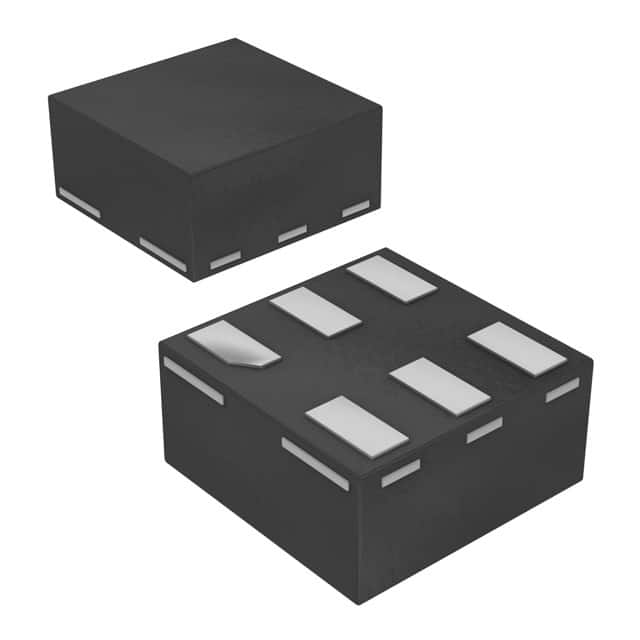
- Package: SOT753 (SC-70)
- Essence: High-speed CMOS technology
- Packaging/Quantity: Tape and Reel, 3000 pieces per reel
Specifications
- Supply Voltage Range: 1.65V to 5.5V
- Input Voltage Range: -0.5V to VCC + 0.5V
- Output Voltage Range: GND to VCC
- Operating Temperature Range: -40°C to +125°C
- Propagation Delay: 3.8 ns (typical) at 2.7V
- Maximum Quiescent Current: 10 µA at 5.5V
Detailed Pin Configuration
The 74LVC1G79GS,132 has a total of 6 pins: 1. Q: Output of the flip-flop 2. D: Data input for the flip-flop 3. CP: Clock input for triggering the flip-flop 4. GND: Ground reference 5. VCC: Positive power supply 6. NC: No connection
Functional Features
- Single positive edge-triggered D-type flip-flop with reset functionality
- High-speed operation suitable for various applications
- Low power consumption
- Wide operating voltage range
- Schmitt-trigger action on all inputs allows slow input transition and better noise immunity
Advantages and Disadvantages
Advantages: - Compact size due to SOT753 package - Wide operating voltage range enables compatibility with different systems - Low power consumption makes it suitable for battery-powered devices - Schmitt-trigger action provides improved noise immunity
Disadvantages: - Limited number of flip-flops in a single package - Not suitable for high-speed applications requiring faster propagation delay
Working Principles
The 74LVC1G79GS,132 is a positive edge-triggered D-type flip-flop. It stores and outputs data based on the clock signal provided at the CP pin. When the clock transitions from low to high (positive edge), the input data at the D pin is captured and stored in the flip-flop. The stored data is then available at the Q output. The flip-flop can be reset to a known state by applying a low level signal to the reset input.
Detailed Application Field Plans
The 74LVC1G79GS,132 is commonly used in various digital systems and applications, including: - Microcontrollers - Data storage devices - Communication systems - Industrial automation - Consumer electronics
Detailed and Complete Alternative Models
Some alternative models that can be considered as replacements or alternatives to the 74LVC1G79GS,132 are: - SN74LVC1G79DBVR (Texas Instruments) - MC74VHC1G79DTT1G (ON Semiconductor) - 74AUP1G79GW (NXP Semiconductors) - TC7SET79FU(TE85L,F) (Toshiba)
Note: This list is not exhaustive, and there may be other suitable alternatives available in the market.
Word count: 346 words
Wymień 10 typowych pytań i odpowiedzi związanych z zastosowaniem 74LVC1G79GS,132 w rozwiązaniach technicznych
Sure! Here are 10 common questions and answers related to the application of 74LVC1G79GS,132 in technical solutions:
Q1: What is the function of the 74LVC1G79GS,132? A1: The 74LVC1G79GS,132 is a single positive-edge triggered D-type flip-flop with reset. It can store a single bit of data and has a reset input for clearing the stored value.
Q2: What is the operating voltage range of the 74LVC1G79GS,132? A2: The 74LVC1G79GS,132 operates within a voltage range of 1.65V to 5.5V.
Q3: How many inputs does the 74LVC1G79GS,132 have? A3: The 74LVC1G79GS,132 has three inputs - D (data input), CP (clock input), and R (reset input).
Q4: What is the maximum clock frequency supported by the 74LVC1G79GS,132? A4: The 74LVC1G79GS,132 can support clock frequencies up to 125 MHz.
Q5: Can the 74LVC1G79GS,132 be used in both digital and analog circuits? A5: No, the 74LVC1G79GS,132 is specifically designed for digital applications and should not be used in analog circuits.
Q6: What is the typical propagation delay of the 74LVC1G79GS,132? A6: The typical propagation delay of the 74LVC1G79GS,132 is around 4.5 ns.
Q7: Is the 74LVC1G79GS,132 compatible with other logic families? A7: Yes, the 74LVC1G79GS,132 is compatible with both CMOS and TTL logic families.
Q8: Can the 74LVC1G79GS,132 be used in high-speed applications? A8: Yes, the 74LVC1G79GS,132 is suitable for high-speed applications due to its low propagation delay and high clock frequency support.
Q9: What is the power supply current consumption of the 74LVC1G79GS,132? A9: The power supply current consumption of the 74LVC1G79GS,132 is typically around 2.5 mA.
Q10: Are there any specific precautions to consider when using the 74LVC1G79GS,132? A10: It is important to ensure that the voltage levels applied to the inputs and outputs of the 74LVC1G79GS,132 are within the specified operating range to prevent damage. Additionally, proper decoupling capacitors should be used to minimize noise and ensure stable operation.